참고 사이트
https://backback.tistory.com/35
http://www.technoblogy.com/show?25TN

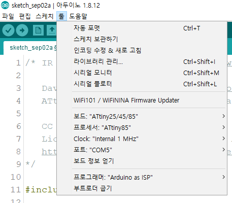
ArduinoISP로 세팅, 부트로더 굽기, 송신기 프로그램 tiny85에 업로드, arduino uno 에서 수신 테스트

수신 소스=====================================================
/*
source: www.electroschematics.com
You'll need to change the led pins and the codes
accordingly to your configuration and IR remote
*/
#include <IRremote.h>
int RECV_PIN = 3; // the pin where you connect the output pin of TSOP4838
int led1 = 2;
int led2 = 4;
int led3 = 7;
int itsONled[] = {0,0,0,0};
/* the initial state of LEDs is OFF (zero)
the first zero must remain zero but you can
16.change the others to 1's if you want a certain
led to light when the board is powered */
#define code1 63495 // code received from button A
#define code2 30855 // code received from button B
#define code3 22695 // code received from button C
IRrecv irrecv(RECV_PIN);
decode_results results;
void setup()
{
Serial.begin(9600); // you can comment this line
irrecv.enableIRIn(); // Start the receiver
pinMode(led1, OUTPUT);
pinMode(led2, OUTPUT);
pinMode(led3, OUTPUT);
}
void loop() {
if (irrecv.decode(&results)) {
unsigned int value = results.value;
switch(value) {
case code1:
if(itsONled[1] == 1) { // if first led is on then
digitalWrite(led1, LOW); // turn it off when button is pressed
itsONled[1] = 0; // and set its state as off
} else { // else if first led is off
digitalWrite(led1, HIGH); // turn it on when the button is pressed
itsONled[1] = 1; // and set its state as on
}
break;
case code2:
if(itsONled[2] == 1) {
digitalWrite(led2, LOW);
itsONled[2] = 0;
} else {
digitalWrite(led2, HIGH);
itsONled[2] = 1;
}
break;
case code3:
if(itsONled[3] == 1) {
digitalWrite(led3, LOW);
itsONled[3] = 0;
} else {
digitalWrite(led3, HIGH);
itsONled[3] = 1;
}
break;
}
Serial.println(value); // you can comment this line
irrecv.resume(); // Receive the next value
}
}
출처: https://backback.tistory.com/35 [Back Ground]
송신 소스=====================================================
아래 소스를 이용하였습니다.
/* IR Remote Wand v2 - see http://www.technoblogy.com/show?25TN
David Johnson-Davies - www.technoblogy.com - 13th May 2018
ATtiny85 @ 1 MHz (internal oscillator; BOD disabled)
CC BY 4.0
Licensed under a Creative Commons Attribution 4.0 International license:
http://creativecommons.org/licenses/by/4.0/
*/
#include <avr/sleep.h>
// IR transmitter **********************************************
// Buttons
const int S1 = 4;
const int S2 = 3;
const int S3 = 5; // Reset
const int S4 = 2;
const int S5 = 0;
const int LED = 1; // IR LED output
// Pin change interrupt service routine
ISR (PCINT0_vect) {
int in = PINB;
if ((in & 1<<S1) == 0) Send('M', 0x0707, 0xFD02);
else if ((in & 1<<S2) == 0) Send('M', 0x0707, 0xFB04);
else if ((in & 1<<S4) == 0) Send('R', 0x0013, 0x0011);
else if ((in & 1<<S5) == 0) Send('R', 0x0013, 0x0010);
}
const int top = 25; // 1000000/26 = 38.5kHz
const int match = 19; // approx. 25% mark/space ratio
// Set up Timer/Counter1 to output PCM on OC1A (PB1)
void SetupPCM () {
TCCR1 = 1<<PWM1A | 3<<COM1A0 | 1<<CS10; // Inverted PWM output on OC1A divide by 1
OCR1C = top; // 38.5kHz
OCR1A = top; // Keep output low
}
// Generate count cycles of carrier followed by gap cycles of gap
void Pulse (int count, int gap) {
OCR1A = match; // Generate pulses
for (int i=0; i<2; i++) {
for (int c=0; c<count; c++) {
while ((TIFR & 1<<TOV1) == 0);
TIFR = 1<<TOV1;
}
count = gap; // Generate gap
OCR1A = top;
}
}
void Send (char IRtype, unsigned int Address, unsigned int Command) {
// NEC or Samsung codes
if ((IRtype == 'N') || (IRtype == 'M')) {
unsigned long code = ((unsigned long) Command<<16 | Address);
TCNT1 = 0; // Start counting from 0
// Send Start pulse
if (IRtype == 'N') Pulse(342, 171); else Pulse(190, 190);
// Send 32 bits
for (int Bit=0; Bit<32; Bit++)
if (code & ((unsigned long) 1<<Bit)) Pulse(21, 64); else Pulse(21, 21);
Pulse(21, 0);
// Sony 12, 15, or 20 bit codes
} else if (IRtype == 12 || IRtype == 15 || IRtype == 20) {
unsigned long code = ((unsigned long) Address<<7 | Command);
TCNT1 = 0; // Start counting from 0
// Send Start pulse
Pulse(96, 24);
// Send 12, 15, or 20 bits
for (int Bit=0; Bit<IRtype; Bit++)
if (code & ((unsigned long) 1<<Bit)) Pulse(48, 24); else Pulse(24, 24);
// Philips RC-5 code
} else if (IRtype == 'R') {
static int toggle = toggle ^ 1;
int nextbit, extended = Command>>6 ^ 1;
unsigned int code = 0x2000 | extended<<12 |
toggle<<11 | Address<<6 | (Command & 0x3F);
TCNT1 = 0; // Start counting from 0
for (int b=0; b<14; b++) {
nextbit = code>>(13-b) & 1;
for (uint8_t i=0; i<2; i++) {
if (nextbit) OCR1A = top; else OCR1A = match;
// Wait for 32 Timer/Counter1 overflows
for (int c=0; c<32; c++) {
while ((TIFR & 1<<TOV1) == 0);
TIFR = 1<<TOV1; // Clear overflow flag
}
nextbit = !nextbit;
}
}
OCR1A = top; // Leave output off
}
}
// Setup demo **********************************************
void setup() {
pinMode(LED, OUTPUT);
pinMode(S1, INPUT_PULLUP);
pinMode(S2, INPUT_PULLUP);
pinMode(S4, INPUT_PULLUP);
pinMode(S5, INPUT_PULLUP);
SetupPCM();
// Configure pin change interrupts to wake on button presses
PCMSK = 1<<S1 | 1<<S2 | 1<<S4 | 1<<S5;
GIMSK = 1<<PCIE; // Enable interrupts
GIFR = 1<<PCIF; // Clear interrupt flag
// Disable what we don't need to save power
ADCSRA &= ~(1<<ADEN); // Disable ADC
PRR = 1<<PRUSI | 1<<PRADC; // Turn off clocks to unused peripherals
set_sleep_mode(SLEEP_MODE_PWR_DOWN);
// Send S3 code on reset
Send('R', 0x0013, 0x000C);
}
// Stay asleep and just respond to interrupts
void loop() {
sleep_enable();
sleep_cpu();
}

